
 This is kind of like COVID sourdough bread for pilots. Seems like many of us undertook this fun project to keep us busy during COVID. As usual, I was a little behind the trend and just finished mine. I’m going to write up how I did mine, hopefully it will help make yours come out better! If you are stopping by because you made a METAR map and it recently stopped working, scroll to the bottom for instructions to fix it.
** UPDATED 10/06/2025 ***
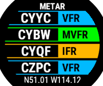
What is a METAR Map? METAR is a format for reporting weather information, and its the format that pilots consume while flight planning or en-route. Most larger airports have their own weather station and distribute METARs concerning the weather at their location. A METAR map uses a small micro-controller to download METAR information from those airports and display it on a map using colored LEDs. For example, green for good weather, red for bad, and other colors in-between.
The end result will look like the image below. In this well lit picture, the green dots may not jump out at you, but those are small LEDs that change color based on the weather in that area. This map displays weather in 13 locations across the map.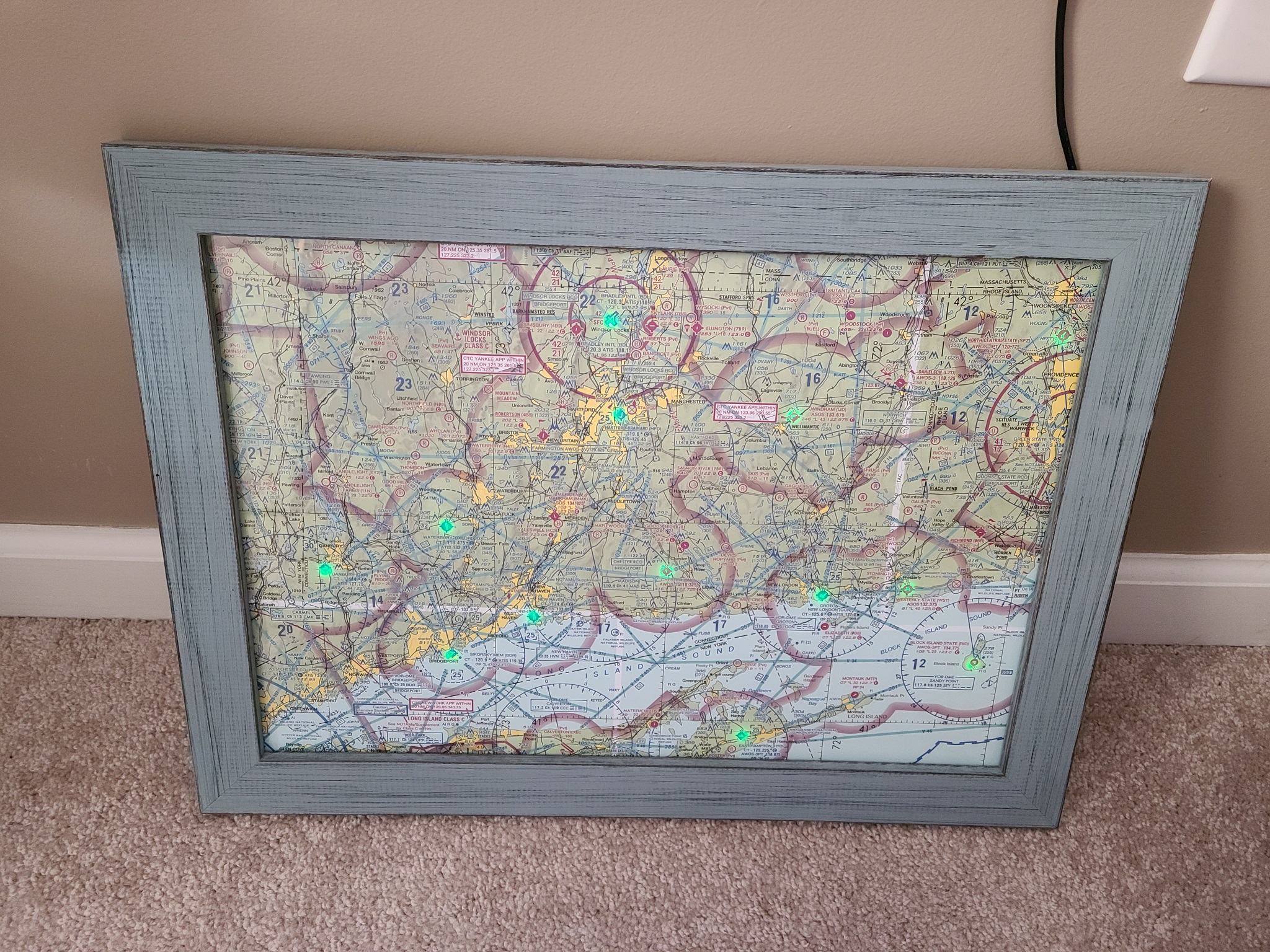
This guide assumes you are using a windows OS and have basic computer skills.
I’ve broken the guide down into 2 parts: Electronics Setup and Physical Construction.
Recommended Tools:
- Hot glue gun
- Soldering Iron
- Foamboard Hole Drill – this will make it much easier to make nice clean holes in your foam-board. Its pricey though if you are only going to make one map.
- Xacto Knife
- Basic Wire Stripper
Materials Required:
- ESP8266 (Node MCU) – This is a little dev board micro controller that you can program with the Arduino IDE. It has built in wifi, takes USB power, and is very small, making it perfect for this project. Don’t worry if you don’t know much about this stuff. We’ll get there.
- A regular micro-usb cable and USB power supply, like you probably have hanging around from an old phone. You’ll use this to power the board.
- Foam Board – You will mount the printed map on this.
- Spray Adhesive – This will nicely adhere the printed map to the foam board.
- Addressable LEDs – here you have a choice. These are the ones I used, they are thinner and probably the best option. The downside is that they come from overseas and might take a month to arrive. These are your other option, which are readily available from Amazon but are a bit thicker.
- A Map – Go here and download the image for the area you want to make a map of. Crop it to the area you want using any image program. Then, resize it to be something like 12″ x 18″ or whatever size you want your finished item to be. I had it printed out at Staples on their heaviest paper using a matte finish. I recommend a heavy paper for this because thinner ones may wrinkle when you glue them down.
Phase 1: Get your Electronics in Order
- Download and install drivers for your board. This will allow your PC to discover it when you plug it in.
- Download and install the Arduino IDE.
- Fire up Arduino IDE.
- Now we need to add the NodeMCU to the Arduino IDE by going to File->Preferences. Look for the field labeled “Additional Board Manager URLs.” In that box, paste in this:
1http://arduino.esp8266.com/stable/package_esp8266com_index.json - Now go into Tools->Boards->Board Manager. In the search box, type “ESP8266”, which is actually one of the chips (wifi) on your board. Click on the one that comes up, and click “install”. If you are having problems with this part, here is a more detailed tutorial.
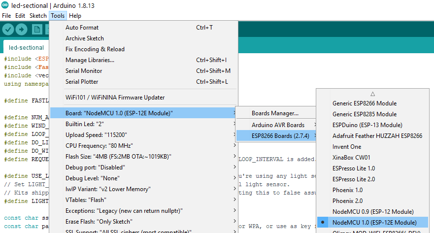
- Select the board as a NodeMCU which might be under a submenu labeled ESP8266 as shown below.
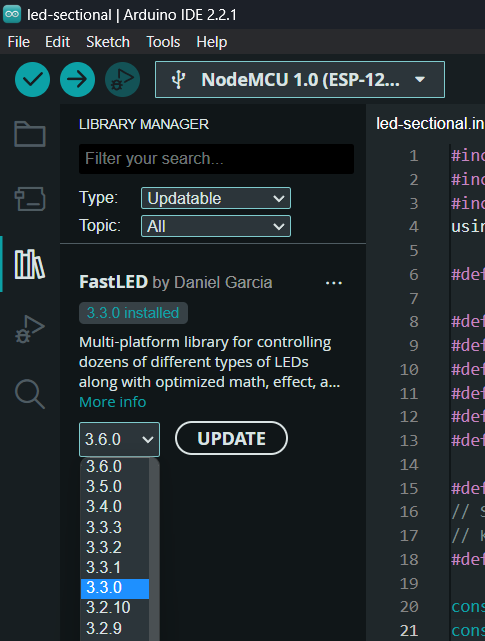
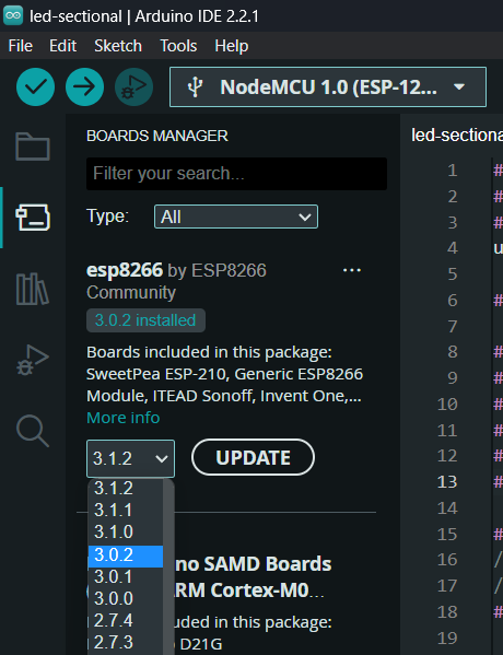
- Code versions matter. I suggest using esp8266 version 3.0.2 and FastLED version 3.3.3. You can choose which version of FastLED to use by going to Tools -> Manage Libraries -> select FastLED and choose what version you want to use, as shown below:
- You can select which version of ESP8266 you use by going to Tools -> Board -> Boards Manager and selecting the version you want, as shown below:
- Kyle Harmon has a great codebase to handle this. I played with some others, and this was the best. This is the actual file you need. Find the rest of the project here: https://github.com/WKHarmon/led-sectional
- The project relies on the FastLED library for LED control. Download that here. Copy it into your Arduino Libraries folder in Your Documents\Arduino\libraries\FastLED
- Open up the led-sectional.ino in Arduino, and you’ll need to do some editing. There are some variables at the top of the file that you need to update. Here are the edits you need to make:
- Look for “NUM_AIRPORTS” and set that to how many LEDs will be in your map.
- Look for these lines, and configure them with your WIFI info:
|
1 2 |
const char ssid[] = "MYSSID"; // your network SSID (name) const char pass[] = "MY_WIFI_PASSWORD"; // your network password (use for WPA, or use as key for WEP) |
-
- If you got the thinner LED from Aliexpress, then look for #define LED_TYPE and set it to WS2812B. It should look like this:
|
1 |
#define LED_TYPE WS2812B |
-
- If you got the thinner LED from Aliexpress, then look for #define COLOR_ORDER and set it to GRB. It should look like this:
|
1 |
#define COLOR_ORDER GRB |
- Edit the list of airports to be the ones you want to light up on your map. Make sure your airport reports weather through aviationweather.gov. You can do this by going to the URL below, editing the KJFK at the end of the sample URL below with the airport code you want to use. If the airport is supported, you will get METAR data in an XML type format. If the airport data isn’t available, it the XML structure will be empty, so don’t use that airport.
|
1 |
https://aviationweather.gov<span class="crayon-p">/cgi-bin/data/dataserver.php?dataSource=metars&requestType=retrieve&format=xml&hoursBeforeNow=3&mostRecentForEachStation=true&stationString=KFJK</span> |
- Finally, you just need to upload this code to your board. Go to sketch->upload and cross your fingers while you wait for it to do its thing. If all goes well, move on to the next step. If there are errors, troubleshoot them!
- Note: If your board is not showing up in your PC device manager, or the port is not showing up in your Arduino IDE, or you are getting ESPTOOL.PY errors, or anything else that seems like it could be related to connectivity, the first thing to try is changing your cable. Many micro-USB cables are for charging only and are not suitable for data. Try a different cable as a first step.
- Wire this thing up to test it before you build everything. If you are using the thinner LEDs from Aliexpress, connect the wires like this:
LED RED WIRE => 3v3 pin on your NodeMCU
LED GREEN WIRE => D2 pin on your NodeMCU
LED BLUE WIRE => GND pin on your NodeMCU
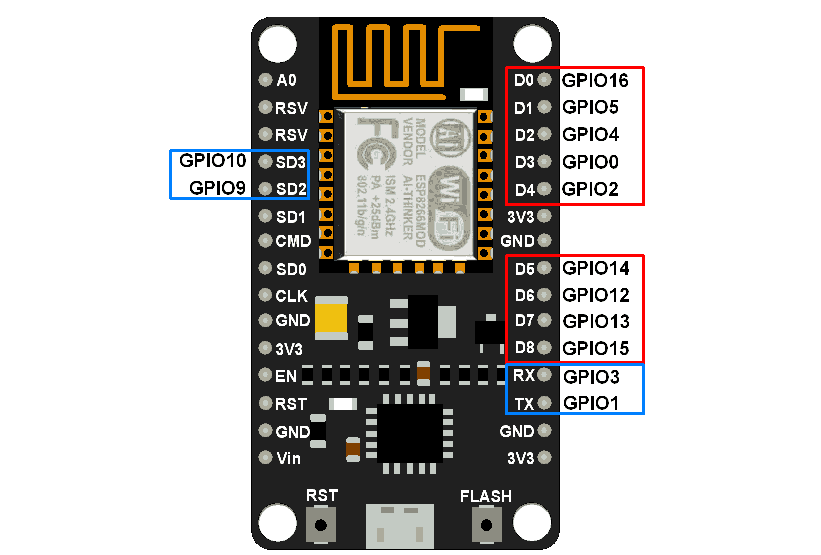 Note: in the image above that the port numbers don’t match what is printed on the board. For example, GPIO14 is labeled D5 on the board. In the code, you’ll want to use the GPIO numbers, not the ones that are printed on the board.
Temporarily connect those wires, then plug it into your laptop and make sure everything lights up! If not, its time to troubleshoot. A hint: you may want to learn about the Arduino serial monitor for troubleshooting purposes.
Phase 2: Physical Construction
- Line your printed map on top of your foam board. Mark on the foam board where each airport is. I did this by using an extra copy of the map, and sticking a nail through each airport and through the foam-board.
- Create a hole through the foam board where each airport is. If you have one, use your Foamboard Hole Drill.
- Spray the foam-board with the Spray Adhesive. Then affix the map to the foam-board.
- Use your Hot glue gun around the LEDs to secure them in the holes. The thinner ones from Aliexpress have a nice bit of circuit board that provides a good surface to glue on. If the space between your airports is too long, you can cut the wires, and splice in extensions. Carefully crimp or solder the wires, then hot glue the connections in place. I also suggest hot gluing the wires down at various intervals to secure them.
- Wire in your NodeMCU like you did before, this time, do it securely, I’d suggest soldering in place.
- I removed all the extra pins from my NodeMCU to make it thinner. For the pins that remain, bend them sideways. See the image below for how the backside of my board looks. Not the prettiest thing, but nobody will see it!
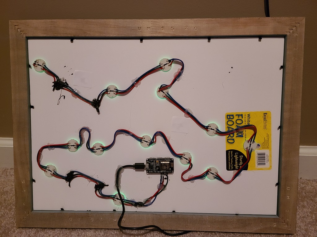
- Hot glue the NodeMCU right onto the posterboard. Plug the USB cable that will ultimately be your power cable in, and hot glue it down to reduce stress.
- Place this whole thing into a frame. I used this one. That is a 12×17″ frame in Dixie Gray color, which arrived quickly. I cut my map to fit the frame.
- Plug it in, fingers crossed! I hope it worked for you!!
** UPDATE May 2023 **
Brian C wrote in to let me know that the current version of FastLED may have some issues. His build was not functional using FastLED version 3.5, but once he swapped in FastLED 3.3 it started working correctly. If you are having issues with your LEDs staying bright white, displaying the wrong colors, or not updating – try out an older version of FastLED.
I received a few other notes that suggest trying different data pins, depending on the specific controller you are using. One person suggested that pin D2 didn’t work for them, but D5 did. Another suggested that Data_Pin 0 didn’t work, but LED_PIN 0 did work. If you are having issues such as the lights flickering or not lighting up at at all, verify what pins you are using.
**** Update October 6 2025 ****
The data format for the Aviation Weather website changed. If you have an existing METAR map that stopped working recently, all you have to do is update to the newest version of the code from Kyle Harmon, located here: https://github.com/WKHarmon/led-sectional. Kyle updated the code on September 17th 2025 for the new URL.
If you’ve customized your code already and don’t want to start from scratch, you can easily update your version by searching for this line:
|
1 |
#define BASE_URI "/cgi-bin/data/dataserver.php?dataSource=metars&requestType=retrieve&format=xml&hoursBeforeNow=3&mostRecentForEachStation=true&stationString=" |
and replace it with this:
|
1 |
#define BASE_URI "/api/data/dataserver?dataSource=metars&requestType=retrieve&format=xml&hoursBeforeNow=3&mostRecentForEachStation=true&stationString=" |
That should fix your issue and get your lights working again.
**** Some Common Troubleshooting ****
Symptom: One light, frequently the first one, that lights up with an incorrect color, at a different intensity, or both.
Fix:
In the beginning of the code, between ESP8266.WiFi.h and FastLED, include the following:
|
1 2 3 4 |
#include #define FASTLED_ALLOW_INTERRUPTS 0 // Used for ESP8266 with WS2812 LED’s. Ugh!!! #define FASTLED_INTERRUPT_RETRY_COUNT 1 #include |
This fix was tested using FastLED v3.2.10 and esp8266 v3.1.2
Credit for this fix goes to Matt Lane, who posted it in the comments below.
Another Fix: Put a random airport that you don’t care about as your first one. Then, cover that LED with electrical tape so you can’t see the light, and just stick it to the back of your map. Now you don’t care if it lights up the wrong color or intensity since nobody can see it.
Symptoms:
- Board not showing in device manager
- Port is not showing up in your Arduino IDE
- Getting ESPTOOL.PY errors
- You get an initial flicker of the lights and then they go dark
Fix: Try a different USB cable to connect to your PC when programming. Many micro-USB cables are for charging only and don’t work for programming the board.
Symptom: Your board is not connecting to wifi
Fix: Are you connecting to a 5Ghz wireless network? The NodeMCU only supports 2.4Ghz wireless.
Symptom: None of your lights are turning on
Fix: Validate that you are using the correct data pin. Note that the pin number to use in code is not the same as the number shown on the board. For example, the pin labeled D1 on the board would be GPIO5 in code. Use the diagram in the post above to verify that your wiring and code are utilizing the same pin.
Good Luck with your build!! If this post was helpful for you, or if you have any questions or comments, please let me know below.
I just saw a map on an FBO wall similar to this and I am interested in making one for myself. Thanks for posting all this and I just ordered the LED’s and accually have a couple of the NodeMCU’s at home.
My METAR map has been on 24×7 for the last 5 months and so far no problems!
Finally, I can see the end of my on again off again project. I did have to leave a led on the back as a dummy because as some below stated the first one seemed to be a random color and just stay bright. It was working at one point but now staying on again. I paired out all the code having to do with the light sensor. A fun trial and error exorcise. However, I would have liked to put one of my real airports first then the key and then the rest of the airports so I wouldn’t have had to splice a long wire to the last one as it was close to the key. Try as I might as soon as I tried to rearrange the airport list the whole thing would go bust. I am still very much a newbie at coding so I have been going through the list to try to understand why the key has to be first. I would guess its in the key segment of the code but not sure. The other hang up was getting a map of my area as I sit right on the edge of KC and Omaha so I would get started then quit after trying to find the map that would print big. I was finally able to find a Tiff file of the 3 areas I needed and put them together and print a high-quality map. Anyway I made 4 as there will probably not be any more due to the cost of putting them together and pain in the but to get the map but I would love to post a picture. Thank you for the great project.
Hey Rick, I’ve been working on my board. I’ve got the first three connections lighting up, but my first LED always is showing “LIFR”. My other two after that are showing VFR as they should, and the first one should be showing VFR as well. Any ideas?
By default, at the top of the list of airports, the code example has the key to the map, where it lists all the colors for each type of weather. The first item in the list is LIFR. I would start by checking my list of airports and making sure I didn’t set LIFR as the first “airport”.
Did you ever get this figured out. I have a similar problem where the first bulb is always green and super intense. Much stronger light than the normal green. I do have the airport correct. All of the others work perfectly. I am using the WS2811 bulbs. Wondering if this is a power issue or a code issue. Same issue on 2 separate light strings I tried
I am having a similar issue where the first LED is displaying a magenta color at full brightness. It seems to be a code issue because I can write a few quick lines to manually assign a color to each led and they show correctly. Any resolution that worked for you?
Did you ever figure this out? I have the same problem. It’s definitely code; but I can’t figure out where. When using the same setup() but replacing loop() with a simple program to flash up a bunch of various color combinations it works fine. Debug shows the proper color in the array right before the show call, so some odd FastLED thing.
Hey Frank,
Similar problem but my first bulb is showing just bright blue. Which is not assigned to any wx condition. Very new to all this, but did you find any solution?
Matt Lane posted a fix for this. Check out the bottom of the post (Common Troubleshooting) for details on how to resolve it.
The Arduino has multiple 3v3 pins and multiple ground pins. Can you advise which pin. One combination lights up one LED only.
Thanks for the comment! I updated the code above to show the various available pins and how to refer to them in code.
Thank you for putting this together it was a great base to get started, I used the same NodeMCU and with a DATA_PIN of 14 in the code, the data output pin is D5, not D2. I would also recommend using a true 5v power supply, I noticed the 3.3v output didn’t work for me that well.
Great tutorial, now I am looking at all the things I can use WS2811 style lights on. The Arduino is a cool thing.
Thanks John, great point. I updated the post above with a diagram to show how the labels on the NodeMCU don’t match the pin to use in code. For example, the pin labeled D5 would be 14 in the code. I guess I always assume that people update the code with whatever pins they are going to actually use in their build.
Hi Rick, I have the WS2811 lights, ESP8266 programmed, the WiFi is working, gathering weather data from the website like it should, but no lights. I’m using pin D2 (GPIO4) for data pin, have it coded that way and nothing lights. When I hook up the power wires up, random lights flicker for about 1/10 of a second. Is there another bit of the code I should be changing to make this work?
Did you ever figure this out? I’m having the same issue and I’m sure it’s something simple
Hello Greg, I am having this same issue and can’t figure out why- random lights flicker for 1/10 of a second when first plugging in then nothing. Did you ever figure this out?
My serial monitor gets all of the METAR data, and then tells me No lighting; going to sleep for: 900000
I tried changing DATA_PIN 14 to LED_PIN 14, also changed it where that variable gets passed later on in the code. Even tried a brand new string of WS2811 lights. Can’t get the lights on at all!
I had that initial flicker when I was first setting up. In my case it was because my COM port was not found. It took me 5 hours just to figure that out. I think it was a combination of many things including that my USB cable did not support data. Very frustrating!
Do I need to change “digitalwrite(LED_BUILTIN, LOW) to something else to get the lights to come on?
I worked on the code for 35-40 hours. Got nothing but yellow lights. Tried every output pin on the board, nothing worked. Without going into detail of the countless other things I tried to make it work, what did make it work was to change DATA_PIN 0 to LED_PIN 0. I’m using a WS2811 LED string and an ESP8266. Just in case someone else would be having troubles.
Need some help as I have the same issues. Where is DATA_PIN 0 in the code?
If you open the code in the Arduino IDE, just search for “#define DATA_PIN”. The issue you and Greg are running into may be that the port currently defined in the code is not the same one you are connected to physically.
In the article above, look at the graphic of the board that shows which ports are which. For example, if you are connecting your lights to the first pin on the right side of the board, labled D0, then you would update the data pin to be 16. Make sure that the pin in your code matches the pin you are actually connecting to.
Thanks to Rick Harmon for the code!!
I’ve tried the works here and I’m pulling my hair out – got the recommended set (thicker WS2811 off Amazon) with an ESP8266 and I can’t get it to pop up at all – I’ve even tried simply using an LED type controller to poll through the lights and still nothing – only thing I can assume is that the WS2811 strip, which flashes ever so briefly same as Greg, is now needing that solid 5V – I’ve tried using D5 as per John, setting to 14 and 5 pin, changing DATA_PIN to LED_PIN in the code – and nothing – going to see if I can somehow find the thinner LEDs without having to ship from aliexpress.
Where you able to install the thinner LEDs to see if that worked? I have the amazon LEDs and cannot get the lights to turn on.
I was checking to see what my various options were for building the METAR board. I have all the hardware from other projects around the house. So my question is the to promising options are via nodemcu or raspberry pi. I would prefer to go the nodemcu path since I have so many boards laying around and only a handful of pi. The pi gives me the option to also display the METAR text in a small screen in addition to the led lights. I haven’t looked at the nodemcu code so I am not sure if this screen addon is doable from the existing Nodemcu code without too many revisions?
This is great. This has been a fun project in trying to learn Arduino. Something new and different as a hobby! I’m aiming to make a good size one, with 50+ airports (spread across two boards and strings of LEDs).
The issue is that I got the board and LEDs connected and got the lights to come on just once while the sketch was loading. Once the upload finishes, the lights immediately go out. The first “airports” in the code are no LIFR or anything else.
Adding to this, the serial monitor just returns ???? too. There’s no other data coming through. I can’t tell if it’s fully connected or not. Any thoughts would be helpful.
Okay… I got the whole thing working, all LEDs are lit, and I see the data coming into the board (via the serial monitor).
The final issue seems to be that the LEDs are not refreshing with the color data — or changing at all. They remain exactly as they were. I can get them to change with simpler programs, but something in the code is preventing the refresh.
Is there a reason they’re not refreshing? What am I missing? It seems like it should be fairly simple.
This is definitely an issue with whatever elements of the code write the LED colors. Something’s not working with this code (or another set I found online).
Not sure what the issue is, but I’ve tried multiple data pins and hard reset the board (including power). Now when the code runs I only just get the first LED as orange.
The LED type is definitely WS2811 and the color order is RGB. There’s a lot of extraneous code for the light sensor but I have that disabled so I don’t think it’s doing anything.
Again, any additional thoughts or troubleshooting for this would be greatly appreciated.
How did everything work out for you Brian?
Rick wrote above “Brian C wrote in to let me know that His build was not functional using FastLED version 3.5, but once he swapped in FastLED 3.3 it started working correctly.”
The 3.3 version is not published https://github.com/FastLED/FastLED/releases?page=1
Anyone have 3.3?
I am getting various errorsDocuments/Arduino/led-sectional/led-sectional.ino:9:1: error: stray ‘\’ in program e
Thank you Rick Harmon for the code. I have the ESP8266 (CP2102) with the WS2812B LEDs. I soldered three lights together, updated the code like the instructions called for, and hooked everything up. All LEDs except the first operate as expected. The first LED is much brighter than the rest and it stays on a specific color depending on the version of FastLED I am using. I’ve tried all versions back to 3.0 but still no luck. Also, I cannot find version 3.4. Any ideas? Thank you!
Just been and looked up the 12 sites in the philippines that have METAR info available RP…. is the codes map is coming and i need to find a piece of foam board. Ibhave loads of node mcu’s so a quick project over xmas when there is time…
Thanks
Steve
Hi Rick,
thanks for that amazing project.
I had a few difficulties but worked them out with the help from the comments.
One Problem is still there. The first Airport is not Showing the right meter condition and is much brighter than the other Leds.
And the first one is actual a airport and not a Metar Condition.
I Use a NODE MCU ESP82666and W2812B LEDs When I run them in the Fast LED Programs, everything is going fine.
Any ideas?
Thanks
Marc
I have a strange issue. I have 10 LEDS to test with and a list of 10 airports.
The result is only the first 9 LEDS light up and it’s with the data from 2-10.
I can do test of all VFR airports and one IFR airport. The result is the IFR airport shows up Red as it should, butg on one LED before the desired LED, leaving LED 10 with no data.
Power on sequence is Orange on 1-9, #10 white
Purple 1-9, #10 white
As a hardware test, I did this:
#include
#define NUM_LEDS 10
#define DATA_PIN 14
CRGB leds[NUM_LEDS];
void setup() {
FastLED.addLeds(leds, NUM_LEDS);
}
void loop() {
leds[0] = CRGB::Red;
leds[1] = CRGB::Green;
leds[2] = CRGB::Blue;
leds[3] = CRGB::Red;
leds[4] = CRGB::Green;
leds[5] = CRGB::Blue;
leds[6] = CRGB::Red;
leds[7] = CRGB::Green;
leds[8] = CRGB::Blue;
leds[9] = CRGB::Red;
FastLED.show();
delay(30);
}
All 10 LEDS light up in that exact order, telling me there’s something wonky in Kyle’s code. I just can’t find it.
Anyone?
Hi Rick, thanks for that great guide.
I’ve build it wit a ESP8266 Node MCU from AZ-Deliverys seems like the Data_Pin is 2 but on the Board it is D4.
If you buy the Boards without pins, there is a bit more Space in the back.
One Failure I still have and do not know how to fix is the wrong color at the first LED.
Any recommendations?
Thanks a Lot Marc
Good question Marc. I’ve added a diagram to the article to show which pins are available and how they should be referred to in code. For example, the pin labeled D4 should be referred to as pin 2 in code.
I often end up cutting the pins off of these boards, didn’t even realize I could buy one without them!
The code treats the first LEDs as like a key or legend. Do you still have that in place? It would cause your first LED to be the wrong color.
I’m hoping someone will be able to help me with this. I am relatively new to this code. I have followed the guide here and tried to set this up with just a single led for now and can’t get anything to light up at all. I’m wondering if it’s this line
std::vector airports({
“K21D”, // 1 order of LEDs, starting with 1 should be KKIC; use VFR, WVFR, MVFR, IFR, LIFR for key; NULL for no airport
});
I just removed the rest of the airports from the example and entered my home airport. Does this need to be numbered?
Also, am I supposed to define the NUM_AIRPORTS in more than one spot?
Thanks in advance for any help
A number helps with knowing exactly how many led’s you have for the total led count. eample:
“K4J6”, // 1 LOGIC lED NOT FOR AN AIRPORT. order of LEDs, starting with 1 should be KKIC; use VFR, WVFR, MVFR, IFR, LIFR for key; NULL for no airport
“K24J”, // 2 Live Oak
“KNIP”, // 3 NAS Jax
“KJAX”, // 4 Jax
“KCRG”, // 5 Craig
“KNRB”, // 6 Mayport
“KFHB”, // 7 Fernindina
“KSSI”, // 8 Saint Simons
That number is for you. the ESP counts it a different way. There is only 1 spot for the NUM_AIRPORTS which is the total number of LEDS you connect including a logic LED if needed. You can see in my code that my first airport listed but that airport does not report weather besides being totally closed. That is where the text about using KKIC comes about. That airport does not report weather either. Before I rolled my esp and fastled drivers back, my first led would be brighter and not the correct color. After research and asking about it, it was thought that the led was acting as somesort of logic. So I put that one behind the map with tape so it could not be seen. Now that I have got the older code to work, it is off/out.
I discovered that mine wouldn’t work when connect to a 5G WiFi network – all lights remained an orangish color and never refreshed. Connecting to 2.4Ghz solved this for me.
I’m also using WS2811 LEDs on pin D5, and FastLED v. 3.4
Good callout Dave, I had the same issue with one of my builds.
I pulled my hair out with this issue. If I assigned a static IP address, things worked, which told me that my router wasn’t handling a DHCP request from the board properly. Some routers in Smart WIFI mode are issues with this board. You can force the board to work as expected by adding these two lines:
WiFi.mode(WIFI_STA);
WiFi.setPhyMode(WIFI_PHY_MODE_11G);
immediately before this line:
WiFi.hostname(“LED Sectional ” + WiFi.macAddress());
Okay so I found out something that may help a few. I decided to go with the thicker LEDs that were purchased off of amazon. After a couple hours of trying to figure out why the lights were not turning on, I decided to read the reviews about the lights. Turns out that they are directional lights and only will work going one direction. I flipped the wiring to the other side of the strand and they worked!!!
Hope this helps!
Finally (mostly) got mine up and running with the Amazon LEDs. Initially had all kinds of trouble controlling the LEDs; even though a simple program that cycles through colors worked fine. Backed off to FastLED 3.3 and it’s mostly good. The first LED is just not behaving. Lights up in a random color at full brightness and stays that way. Anyone have any ideas? For now that one is just left behind the board! Otherwise it works great! Thanks for the design and helpful notes!
I built one for the Philippines. Due to the fast led issues i have rewritten the led handling using neopixel-bus that uses the i2s with DMA access to manage the leds. as above i didn’t use the diming section and i used a final led ( number of airports +1 ) as a holding buffer for the changes and updates due to lightning rain ect 63 airports with iata codes with only 10 reporting on the entire Philippine islands
and yes occasionally the wifi drops i need to figure a response to no wifi that’s visible
Steve, is your code with neopixel posted anywhere? I’d love to try using this instead as I am looking to drive the leds with a Wemos D1.
Hi, I have been working on one of these charts since the end of December. I came across a Facebook post that showed theirs and the led’s they used. After reading this comment section and having similar issues, here is what I have found out to help with issues.
I found an aeronautical map of Georgia through the Georgia DOT website. They used to print these maps but you can download the pdf (large file size) and pull out the map as a jpeg or similar file. I had staples print mine at 24×36. Many other states have similar maps such as Florida, South Carolina, and Tennessee. Some states such as Alabama have a state map showing airport location but the map is not an aeronautical type.
I used these led’s: https://www.amazon.com/dp/B01DC0J0WS?ref=ppx_yo2ov_dt_b_product_details&th=1
I suggest knowing how to solder and to use 24ga solid wire to connect them together if you go this route.
I needed another driver for my computer to see the ESP., the CP210x driver.
You will likely need your first led to be hidden to do what it wants. From what I could find, it is acting as a logic. However, this seems to only occur if you get your chart to work with new software versions of the esp8266 and fastled. I was able to do so some but it would freeze.
It was suggested on the GitHub instructions for where the code comes from to use older drivers. I am using esp8266 ver. 2.7.4 and fastled ver. 3.3.0. To use these older versions, change your data pin back to 5 instead of 14. That is what I had to do to not get an error in Arduino and to be able to upload the sketch to the ESP.
Next, in the code, your first airport needs to account for the logic led so you can put null or name it whatever that does not have weather. I named my K4J6 after the airport I learned to fly at. This led still needs to be considered in your led count. As for example, I have 95 airports and the logic for a total of 96 led’s. The last airport should not have a comma after it. It should look like this:
“KCUB” // 96 COLUMBIA
});
I will have a video up soon about mine to help with this.
[…] I elected to build this project using a NodeMCU, the same board I used in the Metar Weather Map project posted here. […]
I just started building a Metar map. I started with the bullet pixels first to make sure I could make it work. I was having such a hard time until I scrolled down to the comments and saw that rolling back to a older FastLed worked for most people. My lights were working with a base color pallet sketch from Arduino so I knew it was wired and pinned correctly. After finding the 3.0.0 FastLed everything started working. I do have the same issue as others with the very first pixel being full brightness and a random color even with putting Null or an airport that does not report weather. That bulb will just get black tape and hidden behind the map. Now I’m off to learn how to mesh the sectionals together! Thank you for all the info and comments to help others out!
Good thinking on the black tape!
Hi there. New to coding and I am stuck at #9. Open up the led-sectional.ino in Arduino, and you’ll need to do some editing.
Am I supposed to download the led-sectional.ino file? If so, how do I download it…I can only seem to be able to copy that info.
How to download files from GitHub: https://www.howtogeek.com/827348/how-to-download-files-from-github/
Success ! I have built 2 of these so far. One for the house, and another for a buddies hangar. I will build # 3 and donate it to the flight school I spend alot of time around. Some things I did to accomplish the task. I used a dremel tool with a small round cutting bit to make the holes over the airport. On the backside I used a conical sanding bit to enlarge the hole to accommodate the square LED of the LEDS listed above that were used. Instead of hot glue to adhere the led, I used foam safe cyanoacrylate glue (super glue) with the accelerator to glue the entire disc down. I did use a gob of hot glue to hold some wires down. Geographically, I’m located in a super congested airspace area in the Los Angeles sectional, so I ended up having lots of airports with weather available that are right on top of each other. I had to get creative in laying out the lights, including recessing some slightly with the dremel, shortening/lengthening wire, and soldering, over lapping discs of lights over each other, even cutting some of them to allow close spacing. Over all Im so happy with the project, all accomplished with the help of this page and the comments section. I do have one question though.
I would like to set up a user wifi access that can be set by whoever I give the map to (I plan on giving these to fellow pilots for Christmas gifts/birthday gifts) I would like to set it to allow them to put their SSID and password to their wifi without having to hard code in arduino. Does anyone have a super simple way to allow this ?
Thanks again!!
There are a few different options, but none of them are super simple. Here are a few software based ideas: https://www.circuitschools.com/change-wifi-credentials-of-esp8266-without-uploading-code-again/
Another way people solve this is by using a small LCD, like 16×2 and some buttons. Use a library like MenWiz to create a menu that allows editing the SSID. MenWiz has a save function that will store the values in EEPROM, and you just grab those values at the top of the Setup function before you connect to wifi.
Sorry I don’t have an easier solution!
wifi manager library does just this. Sets up as an access point askes you to enter credentials then remembers them you need its library and preferences library it works ok
See this post…
https://stackoverflow.com/questions/74943573/adding-wifimanager-to-metar-map
Nice!! Thanks for posting!
[…] Anleitung gibt es unter Diesem Link von dort aus wird man auf den Code von Kyle Harmon […]
I had many problems with this project, similar to a lot of other people. After a fair amount of headache, I got it working flawlessly. The 2 problems I had were the first LED sticking and I would always have 2 or 3 airports not showing anything, even though they were reporting on aviationweather.gov. It turns out that the newest version of the ESP8266 library has some firmware bugs in it or something. Here are the steps I took to make it all work:
* I had to start by cleaning up my Arduino install to remove the most recent version of the ESP8266 library. I uninstalled Arduino IDE from the windows settings menu then removed the following folders: %appdata%\Arduino IDE, %appdata%\arduino-ide, %localappdata%\arduino15, %localappdata%\arduino-ide-updater, Documents\Arduino.
* Reinstall the newest version of Arduino IDE, which is 2.0.4 at time of writing.
* Download FastLED 3.3.0 from https://www.arduinolibraries.info/libraries/fast-led and install it by going to sketch -> include library -> Add .ZIP Library
* Install ESP8266 2.7.4. This is a bit of a process. I’m sure there’s a lot of ways to do it, but here is what worked for me:
– Make sure you have Git for windows and Python3 installed.
– Go to documents\arduino and make a hardware folder, then make an esp8266com folder in that. Should look like C:\Users\{your user profile}\Arduino\hardware\esp8266com
– Open command prompt and enter ‘cd %USERPROFILE%\Documents\Arduino\hardware\esp8266com’
– Enter ‘git clone https://github.com/esp8266/Arduino.git esp8266′
– ‘cd esp8266’
– ‘git checkout 2843a5a’
– ‘git submodule update –init’
– ‘cd tools’
– ‘Python3 get.py’
– Close command prompt
* At this point, you can follow the rest of the guide with the following changes:
– Change #define DATA_PIN from 14 -> 5. This does NOT change what pin you use on the board – D5
– Do NOT do steps 4 or 5 from the electronics section to set up the board manager. We already installed the board, so just skip these steps entirely!
I think that was all I needed to do to get everything working. I’m no expert on Arduino or anything, but I can certainly try to help if anyone is having problems.
Thanks for posting. I’ve updated the post with instructions on how you can choose various versions of the FastLED and Board software from within the Arduino IDE.
Are you aware of a UK based source of of the METAR data to enable the project to work for uk airfield?
I’ve built 2 maps, one using the WS2812B bulbs, and the other using the WS2811 bulbs. With both maps I am having the same issue with not all of the bulbs lighting at once. I will have at least 2 and up to 4 or 5 bulbs out after a refresh. But it’s always a different set of bulbs that are out when it does its 15 minute refresh. I’ve used different versions of FASTLED and different data pins. Version 3.3 works the best with the WS2811 bulbs and version 3.4 works with the WS2812B bulbs. I’ve never gotten any bulbs to light with FASTLED 3.5. Some airports are on both maps, there are times when an airport will light on one map, but not the other map. All of the code is basically the same except for the LED TYPE and the airports.
I’ve also verified at http://www.aviationweather.gov/adds/dataserver_current/httpparam?dataSource=metars&requestType=retrieve&f
when I bulb is not lit that it is reporting weather.
I don’t know enough about coding to know if the issue exists in FASTLED or the code. I’m also using a 5V power supply. During the startup test they all light up as well.
Any troubleshooting tips would be greatly appreciated.
Thank you for putting the instructions together, your site is the most comprehensive and detailed instructions that I have found!
I just resolved my issue of random lights not lighting after each refresh. I changed the board manager to 2.74 and Data Pin from 14 to 5 in the code. All good now!
I’ve built 4 METAR maps using a couple different Pi models and different software. All work flawlessly. I decided to try out the ESP8266, and had a ton of headaches.
First, wifi would not connect to a SmartWiFi router…and seems some others out there are having this issue. After several hours I fixed that by adding two lines of code before the WiFi.hostname call:
WiFi.mode(WIFI_STA);
WiFi.setPhyMode(WIFI_PHY_MODE_11G);
I know that I should have 17 stations lit up (I’m looking at an existing map on the wall!), but there are only 14. For the life of me, I can’t figure out why. It’s the same airport list that’s working with other software. I’ve got NULL for the first LED due to the issue with the first LED always staying blue.
Am I the only one who noticed this code isn’t actually checking for lightning? Rather, it checks for the string “TS” in the field . It’s quite possible to find “lightning distant”, and no thunderstorms. In that case, an LED will not blink white. The LTG thing is in the field , which is not used in the code at all. I’m trying to fix this.
I enhanced the code to *blink* orange (vs staying on orange) for any airport with high winds, not just VFR airports, and to also blink white if there are thunderstorms. So a single airport can actually have 3 colors…flight category, blink orange for high winds, blink white for thunderstorms.
How are you guys temporarily connecting without soldering? I got the thicker WS2811 and it has a connector itself but then also a 3 lose cable plug I’ve been plugging it into and trying to temp keep the cables connected or touching to figure out which are the right pins
I use the breadboard jumper cables like these: https://amzn.to/3QHlhz6. I take a male to male one, and I use a pair of needle nose pliers to bend the male part into a tiny circle that just barely slides right over the pins on the NodeMCU. Then I can move that jumper around while I’m prototyping without any solder.
In December 22 i built one for the Philippines islands and its 63 airports. i had trouble with the LED driver so rewrote the program using Neopixel-Bus and changing a few things (only 10 sites report in the Philippines)
One thing that became obvious was my map is 1.6M tall and nearly a 1M wide and the power needs reinforcing to the pixels in a few places this shows itself as the blue colour not being as bright and showing more red and data corruption
The node mcu needs to use a specific pin for the pixel output as it uses DMA to shift the data string to the pixels.
The only other thing that is significant is the leds use a spare location at the end of the string. this is used to swap the LED colours when showing a condition like snow or lightning…
It works well
if you want a copy i have a zip file containing teh project. (too lazy to set up a github account) xygax@hotmail.com
I seem to be able to get it to partially work, like vfr, mvfr those codes do change the color. But when I try and put the airport codes in some will work and others don’t but if I change the order or add different ones in between then some of the ones that don’t work start working and others stop…..
Thank you for this awesome tutorial, Rick! I am just getting started. In your code it says:
std::vector lightningLeds;
std::vector airports({
“LIFR”, // 1 order of LEDs, starting with 1 should be KKIC; use VFR, WVFR, MVFR, IFR, LIFR for key; NULL for no airport
“IFR”, // 2
“MVFR”, // 3
“WVFR”, // 4
“VFR”, // 5
“NULL”, // 6
“NULL”, // 7
“KMRY”, // 8
“KSNS”, // 9
“KCVH”, // 10
Should KKIC actually say KMRY?
Hey hey – From Denmark here! Great project 🙂
I’m having some issues with fetching airport-data. In my log it does the following:
23:16:21.613 -> GET /adds/dataserver_current/httpparam?dataSource=metars&requestType=retrieve&format=xml&hoursBeforeNow=3&mostRecentForEachStation=true&stationString=EKCH,EKRK,EKEB,EKBI,EKAH,EKYT HTTP/1.1
23:16:21.644 -> Host: http://www.aviationweather.gov
23:16:21.644 -> User-Agent: LED Map Client
23:16:21.644 -> Connection: close
23:16:21.644 ->
23:16:21.743 -> Getting data
23:16:21.937 -> EKYT: VFR 4G0kts LED 6 WX:
23:16:22.033 -> EKEB: VFR 6G0kts LED 3 WX:
23:16:22.131 -> EKCH: VFR 1G0kts LED 1 WX:
23:16:22.196 -> EKRK: 2G0kts LED 2 WX:
23:16:22.196 -> Refreshing LEDs.
23:16:22.196 -> No lightning; Going into sleep for: 900000
So it basically looks like it’s breaking up after 3 airports. If i change the order of them, just for testing – it still breaks up. I will get lights in the ones shown above (6, 3, 1) except for the halfway done one.. (2). What could be wrong? If i load the string in my browser, the XML shows fine.
Great Job on the explanation! This has been a fun little project! the only issue that I am having is Ive got a large map of Michigan with 90 LEDs and Ive almost got it set but there are 4 or sometimes less airports that will turn off and on randomly after each refresh of the aviation weather and its almost random airports there’s no rhyme or rhythm. Its almost like the chip wont get enough time to read the website data and then it moves on to the next airport website while leaving that airport incomplete (dark). Any suggestions? Thanks!!!
Looks like the aviationweather.gov server has changed over and there has been a code change from Harmon posted 3 hours ago. I’m thinking this is a fix for the issues that the server change caused and caused all of our maps to go inop. Let me know if this is correct, as I’m at work for a couple more days and wont be able to get home to throw the new code lines in the map
I’ve updated the post above with a fix for this issue. Luckily it isn’t too bad. Make sure you keep your library and board versions at the correct levels when you update your map code.
aviationweather.gov changed all of their URLs and METAR Maps will no longer work until they are pointed to the new URL, which I have yet to determine.
Thats right Joel, they changed the format the same day you posted this. I’ve updated the post above with a fix for this issue.
Anyone having issues with the lights not coming on? It seems that the data page isn’t working?
https://aviationweather.gov/adds/dataserver_current/httpparam?dataSource=metars&requestType=retrieve&format=xml&hoursBeforeNow=3&mostRecentForEachStation=true&stationString=KFXE
For those who noticed on 10/16/23 that your map isn’t working, you need to update two lines of coding. The link is below, replace the pink with the green.
https://github.com/WKHarmon/led-sectional/commit/d2265f399e76dc45e15e23fb35ffab70afa7a45c
If it still not working, you will need to change the COM port. How? In your PC’s Device Manager -> Ports (COM & LPT) -> Silicon Labs CP210x , right click Properties, select Port Settings, Advanced and then a new port number.
From the Arduino sketcher, you’ll need to change the port there too (Tools -> Port) to match the new one you selected. Disconnect and reconnect the board from the PC, run the sketcher. If it still doesn’t work….someone way smarter than I will have to help.
After AviationWeather updated their website this week it broke my METAR map I had bought off someone online. They provided no support for it, so I figured I’d work it out myself.
I was able to take the information from this post to upload the updated software from github onto the NodeMCU (ESP12-E/F) used for the project.
I had to DOWNGRADE several libraries to get this to work properly. I was getting white LEDs only (on the first 13 of the 25 leds only, oddly) until I did so.
The DATA_PIN used was D4 as that is what was physically labeled on the NodeMCU.
Working library Versions:
-esp8266 version 3.0.2
-FastLED version 3.3.3
-Vector version 1.2.2
I had issues with the program when using placeholders such as VFR/LIFR/NULL; only when I input valid airport identifiers into the array did the LEDs actually work right. Make sure to test the airport identifier on aviation weather to make sure it shows up. For smaller airports starting with F or L, put a K before them (even if they do not technically have an ICAO code for that airport). Example would be KF70 French Valley, KL18 Fallbrook
Any ideas why I get this code error (see below) when I compile for the ESP8266 utilizing the 2.74 version and FastLED 3.3. Pin is coded as 14 as per instructions. Sketch will compile when pin is 1-10 but wont compile any thing higher. It throws the error when attempting to load on the NODE MCU 1.0, but will load and function on the Espino 12. Perplexed. Thinking something has changed on their end and looking for a fix.
Error code:
c:\Users\jbill\Documents\Arduino\libraries\FastLED/fastpin.h:207:2: error: static assertion failed: Invalid pin specified
static_assert(validpin(), “Invalid pin specified”);
^
exit status 1
Compilation error: exit status 1
All, I discovered today (after hours of investigation) that the aviationweather.gov website was updated on October 16, 2023 (see green notice at the top of https://aviationweather-bldr.ncep.noaa.gov/help/whatsnew). It appears the update broke the METAR XML feed. I finally found an error message: “Our services aren’t available right now. We’re working to restore all services as soon as possible. Please check back soon.” I believe (hope) it is a temporary issue and they will push a fix soon so our METAR maps can start working again. Just FYI.
Thanks for the heads up! I’ve updated the post with a fix for this issue.
I stumbled across a fix for the first led not showing the correct color. In the beginning of the code, between ESP8266.WiFi.h and FastLED, include the following:
#include
#define FASTLED_ALLOW_INTERRUPTS 0 // Used for ESP8266 with WS2812 LED’s. Ugh!!!
#define FASTLED_INTERRUPT_RETRY_COUNT 1
#include
I’m running FastLED v3.2.10 and esp8266 v3.1.2
Awesome! Thanks for sharing that! I will add this to the post above too.
I’ve recently updated the website address and its working perfectly. I have run into a separate issue though. I’ve made a few of these for friends and have recently bought a couple Arduino NodeMCU ESP-12F modules to replace burnt out ESP-12Es. Though I’m using the exact same code as the 12Es, the 12Fs wont bring on a single light. I’m wondering if there is a different version of ESP8266 that I need to run for this different module. I ran 2.7.4 on the 12E and it worked just fine.
I have an airport, KC08, that will not light. It reports a METAR and shows the flight category. I have tested the light with other airports, and it does work. But for some reason this identifier will not. Has anyone else run into this with an airport? KCZero8
https://aviationweather.gov/cgi-bin/data/dataserver.php?dataSource=metars&requestType=retrieve&format=xml&hoursBeforeNow=3&mostRecentForEachStation=true&stationString=KC08
Seems like my board will update fully now after a power cycle but after sometime it remains on the colors shown and does not update anymore? Thoughts?
Is there anyway to add a legend to the map? Say the first 4-5 LEDs to show what each color means?
I added a legend by placing “VFR” “MVFR” “IFR” “LIFR” and “WVFR” in the respective LED spot.
Could you use two strings of LEDs back to back with just one board? Or is there a limit to how many lights one board could run? (I’m using the AliExress thin lights with the ESP8266).
Many thanks for putting this out there, much appreciated!
I’m running esp8266 2.7.4 with FastLED-3.3.0 and have tried multiple combinations of boards/FastLED but I cannot get the colors blue or white to show up; All of the LEDs that should be purple are red, blue does not show up at all, and the white lightning flashes are yellow. Has anyone encountered this before?
Anyone have one led blink a white about every 5 seconds?
Btw – I was able to hook a couple of strands back-to-back, and has worked so far, so it looks like that is possible. (unless this blinking is a result of overloading them lol).
any ideas on how to get a Led to blink yellow and current status when winds go above a certain speed?
So I got the Amazon lights and I want to know where to plug them into the boards. Is there a chart?
Yup. Just scroll up.
Red goes to the pin labeled 3v3 on the NodeMCU, Green goes to the pin labeled D2, and Blue goes to the pin labeled GND.
Any ideas on how to get a Led to alternatively blink yellow and current VFR/IRF status when winds go above a certain speed?
I just wanted to say thank you for taking the time to write all this up in a step by step style. I do know it appears the last up date was in 2023. Would you still use the same electronics and led lights today? I’m about do this and I really can’t say enough how much I appreciate this. You made me want to try something I absolutely, no nothing about and.I believe I can accomplish this project.
I am getting the following errors…any help greatly appreciated.
In file included from C:\Users\roryc\OneDrive\Documents\Arduino\sketch_sep8a\led-sectional.ino:2:
c:\Users\roryc\OneDrive\Documents\Arduino\libraries\FastLED/FastLED.h:14:21: note: ‘#pragma message: FastLED version 3.003.000’
14 | # pragma message “FastLED version 3.003.000”
| ^~~~~~~~~~~~~~~~~~~~~~~~~~~
In file included from c:\Users\roryc\OneDrive\Documents\Arduino\libraries\FastLED/FastLED.h:65,
from C:\Users\roryc\OneDrive\Documents\Arduino\sketch_sep8a\led-sectional.ino:2:
c:\Users\roryc\OneDrive\Documents\Arduino\libraries\FastLED/fastspi.h:130:23: note: ‘#pragma message: No hardware SPI pins defined. All SPI access will default to bitbanged output’
130 | # pragma message “No hardware SPI pins defined. All SPI access will default to bitbanged output”
| ^~~~~~~~~~~~~~~~~~~~~~~~~~~~~~~~~~~~~~~~~~~~~~~~~~~~~~~~~~~~~~~~~~~~~~~~~~~~~~~~
C:\Users\roryc\OneDrive\Documents\Arduino\sketch_sep8a\led-sectional.ino:109:6: error: redefinition of ‘void setup()’
109 | void setup() {
| ^~~~~
C:\Users\roryc\OneDrive\Documents\Arduino\sketch_sep8a\sketch_sep8a.ino:2:6: note: ‘void setup()’ previously defined here
2 | void setup() {
| ^~~~~
C:\Users\roryc\OneDrive\Documents\Arduino\sketch_sep8a\led-sectional.ino:172:6: error: redefinition of ‘void loop()’
172 | void loop() {
| ^~~~
C:\Users\roryc\OneDrive\Documents\Arduino\sketch_sep8a\sketch_sep8a.ino:7:6: note: ‘void loop()’ previously defined here
7 | void loop() {
| ^~~~
exit status 1
Compilation error: redefinition of ‘void setup()’
I tackled updating my Metar for the web address change. I also upgraded to the code with improved wind and lightning effects. The chart is now like a Christmas tree with blinking lights! I got the new code here:
https://github.com/jcl-rv12is/led-sectional
I did add some code to this ino for what I could find for wifimanager. At first, it would bring up the access point, but none of my devices would stay connected long enough to do anything. I added to the code and now my Metar has somehow connected to the internet, and I am not sure how. The test will be when I take it back and try to connect to a different network.
Anyone want to proof or recommend where I can post the code to be proofed and improved if needed?
I’ve got the strangest issue. Seems like with both maps I’ve build (thanks BTW for posting the great info!) no matter what I do – there are always 2 (or so) LEDs that decide to not light. At first I thought it was just that the particular stations are not reporting… but when I alter the non-lighting LEDs by assigning nearby airport designations – then they work.. but a different couple of lights do dark. I’ve tried varying the “num of airports” to plus or minus the exact number (including the correct number plus the legend and LED 0) but nothing seems to help. Anyone had that issue before? Thanks!
In the steps below, where do I find the “preferences” tab on a Mac? I don’t see a “file” and “preferences”, therefore I can’t add arduino board manager
“1: Get your Electronics in Order
Download and install drivers for your board. This will allow your PC to discover it when you plug it in.
Download and install the Arduino IDE.
Fire up Arduino IDE.
Now we need to add the NodeMCU to the Arduino IDE by going to File->Preferences. Look for the field labeled “Additional Board Manager URLs.” In that box, paste in this:
1
http://arduino.esp8266.com/stable/package_esp8266com_index.json”
Loved making my board. It’s a simple project l, yet looks amazing in my office.
I made a board for a friend. His stopped working when the FAA changed their servers. I was able to get things working again recently for mine, but his still does not work. I verified his WiFi SSID/password and even changed the chip out with mine, just changed the WiFi information. He has the exact same code as my board.
Could it be his internet settings, or am I missing something else?
Most boards only work on 2.4 GHz Wifi, if his network only transmits on 5, that is the issue.
Well, the aviationweather.gov URL changed yet again, and my map went dark!
Many thanks to Kyle Harmon for providing the new URL found here:
https://github.com/WKHarmon/led-sectional/commit/cd43d6182292ff80636c9df2b2b29e0f3eabe5cf
HOWEVER, after applying the suggested edits less than half the airports on my map light up, and the rest remain dark. The pattern changes with every refresh, but it’s quite disheartening to see a mostly dark map, anyone else experiencing this?
Thanks!
Did you have any luck with this? I just updated mine and have exactly the same issue of random LEDs are dark. I enabled debug and monitor the debug output via the serial monitor (Arduino IDE) and can see that the airports that are dark *are* getting weather data from the API response…but they’re randomly not turning on.
The same is happening to me.
Rick,
I have built 4 of these now, 1 for me and 3 I gave away. I should have looked here as I see someone posted for adding the ability to change Wi-Fi without re-uploading. I did the same, but it took me about 5 months of studying the code from a simple sketch to do that and to get it all added to this sketch without crashing something. I still wish I could get my head around and truly understand the code and how it all works. However, FAA changed the API stuff again and if anyone has figured out how to change the lines to make it work again i would be grateful for the help. In the meantime, I will keep plucking away and maybe get it figured out.
I now have a functioning. Im not sure how to put on Github or anything but thanks to Claude ai and a lot of trial and error. We have it fixed and working. Claude cleaned it up a lot and took my two mashed up files and created a clean copy. It also has the ability to change the Wifi without having to recode.
I have been fighting this issue since Sept 24! I have two panels for my flight school. Both quit! I had the same problem two years ago when the government changed the code. It took me a week to fix both of my panels. This time it’s been over a month. Today I’m just getting the first light to come on —white, then blue, then green. I have checked the WiFi, and it’s on 2.4 GHz. I have had numerous coding problems with Kyle’s code on my Arduino. Mostly not getting the correct sequence of files into the unit. Any ideas or help would be very much appreciated.
Hi Alan, I’ve been trying to understand the Metar code for a few days now, but I’ve failed. Luckily, I came across your post. Would you please send me your working code? Best regards, Florian
Been thinking about making this project for quite a while. I saw another person had added an OLED display, but they were using a RasPi. I’m using an ESP8266 like you and I was wondering if you knew how to add the display? It looks like it would use the D1 and D2 pins, but in your wiring diagram the LED lights are using those 2 pins.