
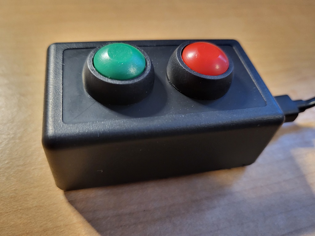
I had a need for a device that would send an email at the push of a button. I also needed it to send a different email when I push a different button. My use case here is related to a Homeowners Association (HOA) that requires me to “check-in” on arrival and “check-out” on departure. In this case, that is done via email. So, I wanted a device with a “check-in” button and a separate “check-out” button, so I could just push those buttons to satisfy the requirements. The the finished product is shown at left.
What Does This Project Do?
The outcome of this project is a small enclosure with 2 buttons on it. I’m going to use one green button and one red button. If you press the green button, it will send a specific email. If you press the red button, it will send a different email. In my use case, the green button will “check me in” and the red button will “check me out”. You could repurpose this project with almost any quantity of buttons and messages for nearly any purpose.
Another potential use case could be a “silent alarm” or emergency type button. You could configure the device to send a status email to a contact – press the green button if you are doing OK and press the red button if there is an issue.
After some research, it looks like many people send emails from their boards using things like IFTTT.com. While that would probably be simpler, I didn’t want to have external requirements to keep track of. Instead, I’m going to use an SMTP client library to send email, which we’ll discuss below.
I elected to build this project using a NodeMCU, the same board I used in the Metar Weather Map project posted here. I’m a fan of this board because it is small, has built-in wifi, and is compatible with the Arduino IDE. The total cost of this project is very low thanks to the low cost of the NodeMCU. You should be able to put one of these together for about: $7.45.
$5.30 for the NodeMCU
$1.50 for two 12mm buttons
$0.65 for the project box
——————————-
$7.45 total cost per device at the time of writing
** UPDATE ** I added some status LEDs to this device in a new post located here.
I’ve broken the guide down into 2 parts: Electronics Setup and Physical Construction. Lets get started!
Recommended Tools:
Materials Required:
- ESP8266 (Node MCU) – This is a little dev board micro controller that you can program with the Arduino IDE. It has built in wifi, takes USB power, and is very small, making it perfect for this project. Don’t worry if you don’t know much about this stuff. We’ll get there.
- A regular micro-usb cable and USB power supply, like you probably have hanging around from an old phone. You’ll use this to power the device.
- Buttons – I used these colored 12mm buttons. They are a good fit for the project enclosure I’m using.
- Project box – This tiny project box fits the NodeMCU and 2 buttons perfectly.
- Hookup wire – to connect your buttons to your NodeMCU.
Phase 1: Get your Electronics in Order
- Download and install drivers for your board. This will allow your PC to discover the NodeMCU when you plug it in.
- Download and install the Arduino IDE.
- Fire up your Arduino IDE.
- Now we need to add the NodeMCU to the Arduino IDE by going to File->Preferences. Look for the field labeled “Additional Board Manager URLs.” In that box, paste in this:
http://arduino.esp8266.com/stable/package_esp8266com_index.json
- Now go into Tools->Boards->Board Manager. In the search box, type “ESP8266”, which is actually one of the chips (wifi) on your board. Click on the one that comes up, and click “install”. If you are having problems with this part, here is a more detailed tutorial.
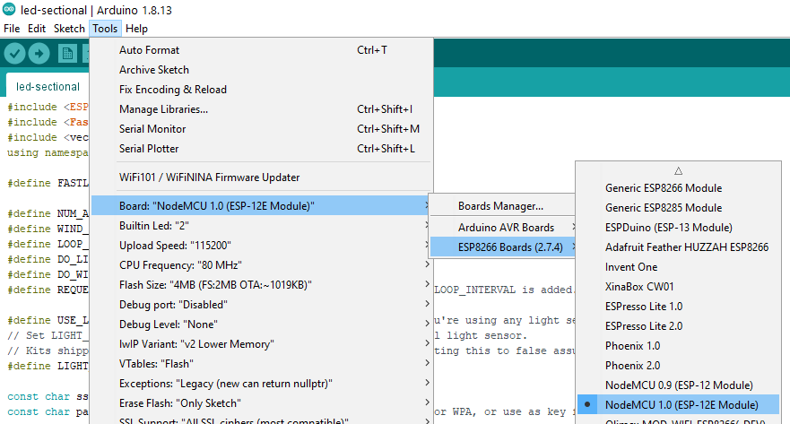
- Select the board as a NodeMCU which might be under a submenu labeled ESP8266 as shown below.
- The project relies on the ESP-Mail-Client project from Mobitz. Download that library here.
- In the Arduino IDE, go to Sketch –> Include Library -> Add .ZIP Library.
- Select the ESP-Mail-Client .zip file that you downloaded to import it.
- Grab the code from my Github repo here.
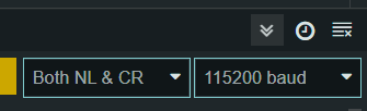
- Lets make sure our serial monitor is setup correctly. If you look at the right hand side of your IDE, you’ll see this section where you can select a speed. The code sets the serial speed to 115200 baud, so set this dropdown box to match:

- For your Email, you can use pretty much any email provider. I used GMail, and created an account specifically to live on this device. One thing to be aware of if you are using GMail is that you need to enable an app password. This tutorial has nice instructions on how to do that, as well as some info for other popular email providers.
- Next we need to update some variables in the code, so lets walk through those here. Open up the .ino file you just downloaded in the Arduino IDE.
- Locate this block of code, and update with your own WIFI SSID, WIFI Password, Email Account, and Email Account Password:
12345678910/* Update these values with your WIFI information */#define WIFI_SSID "YOUR SSID HERE"#define WIFI_PASSWORD "YOUR WIFI PASSWORD HERE"/* Update these values with your Email Sending Account information */#define SMTP_HOST "YOUR SMTP HOST HERE"#define SMTP_PORT 465 //Update to whatever SMTP port you are using/* The sign in credentials for sender account */#define AUTHOR_EMAIL "SENDER EMAIL"#define AUTHOR_PASSWORD "SENDER EMAIL PASSWORD" - Scroll down a bit to find this next block. These are the messages and subjects for the emails you are going to send. Edit them to your needs. Note that you CAN use HTML in the message text.
12345678if (inbuttonState == LOW) {Serial.println("Check-In Button Was Pushed");SendEmail("This is the text for the check-in button email", "Check-In Subject"); //Edit with your message text}if (outbuttonState == LOW) {Serial.println("Check-Out Button Was Pushed");SendEmail("This is the text for the check-in button email", "Check-Out Subject"); //Edit with your message text} - Finally, scroll down a bit more to find this block. Edit this with your recipient information.
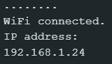
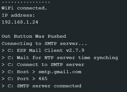
12345message.sender.name = F("YOUR NAME"); //edit with the name of the sendermessage.sender.email = AUTHOR_EMAIL;message.subject = MessageSubject;//edit with the email address you are sending tomessage.addRecipient(F("NAME OF RECIPIENT"), F("recipient@whatever.com")); - Now you just need to upload this code to your board. Go to sketch->upload and cross your fingers while you wait for it to do its thing. If all goes well, move on to the next step. If there are errors, troubleshoot them! If it works, you should see something like this in the serial monitor, indicating that you are on the WIFI and have an IP address. That is all this sketch will do until we get the buttons hooked up in the next section.
Phase 2 – Physical Construction
- First, wire up your buttons as shown below. I’d suggest just using a breadboard or some hookup wires to temporarily connect everything and make sure it works. Once its wired up, you should be able to do a full test. Go to sketch->upload and wait for it to compile and upload, just like we did in the last step. If you push one of those buttons, it should send you an email – try it out!
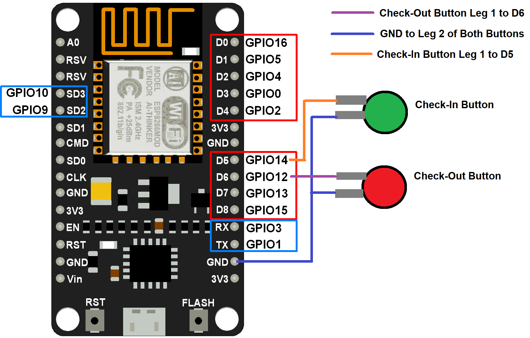 Note: In the image above that the port numbers don’t match what is printed on the board. For example, GPIO14 is labeled D5 on the board. In the code, you’ll want to use the GPIO numbers, not the ones that are printed on the board. For example, here is what the code would look like if I exactly match the above diagram:
|
1 2 3 4 5 |
// set pin numbers const int checkinPin = 14; //aka Pin D5 the number of the pushbutton pin const int checkoutPin = 12; //aka Pin D6 the number of the pushbutton pin const int greenLED = 13; //aka pin D7 for the success LED const int redLED = 15; //aka pin D8 for the error LED |
Note: The pins describing the LEDs are for if you build the version that includes status LEDs. Once you finish this guide, head on over here to add LEDs.
Note: You don’t need to include a resistor because the NodeMCU supports an internal pullup on some ports. Here is an article explaining a bit more about the internal pullup. You can see this feature being enabled in the code here:
|
1 2 3 |
// initialize the pushbutton pin as an input pinMode(checkinPin, INPUT_PULLUP); pinMode(checkoutPin, INPUT_PULLUP); |
- If everything compiled and uploaded properly, and you have your hardware and code setup correctly, you’ll see something like this in your serial monitor. You’ll also receive the email!

- Ok, looks like everything is working. Now its time to put the project together. First, drill 2 x 12mm holes into your project box. Mount your buttons into those hole using the included nuts and washers.
- I’m going to use hot glue to keep the board stable in the project box. I know there are better ways, but this is a quick project for something that is very unimportant so I’m taking the easy way out.
- I’m connecting my cable inside the project box and gluing it to the box. Drill a hole in the side of the box to put the cable through. Glue it down a bit inside for some pull resistance.
At this point, you should have a cool little device with 2 buttons that sends a different email depending on which button you push. If you would like to have some LEDs on the device that let you know if the email was sent successfully or not, head on over to this post, where we add those LEDs!
Have any questions or comments? Let me know in the comments below!
[…] putting this email button device into service, I discovered that I really wanted some instant feedback to know if the email was sent […]
The links are a little confusing, what gauge wire do you need to connect buttons to the NodeMCU? The project box link goes to a 22 AWG, 6 color pack of wire . I’ve never soldered before so not sure if that’s too thick/thin, etc
22 AWG wire is fine here. Any 22 AWG wire would be fine. Using multiple colors may help you troubleshoot but is not required.
Very nicely explained.
I started with ESP8266 in my hand for the first time yesterday and have it all up and running today.
Never seen or used one before. I know NOTHING about programming but made it work.
How about sending to more than ONE recepient?
(not using CC or BCC)
I’m building a sewege level varning system for me and 2 neighbours and would like them all to get a mail when the shit hits the fa… I mean the level is to high.