
 After putting this email button device into service, I discovered that I really wanted some instant feedback to know if the email was sent successfully or not. I decided to add some LEDs into the mix that would illuminate on success or failure.
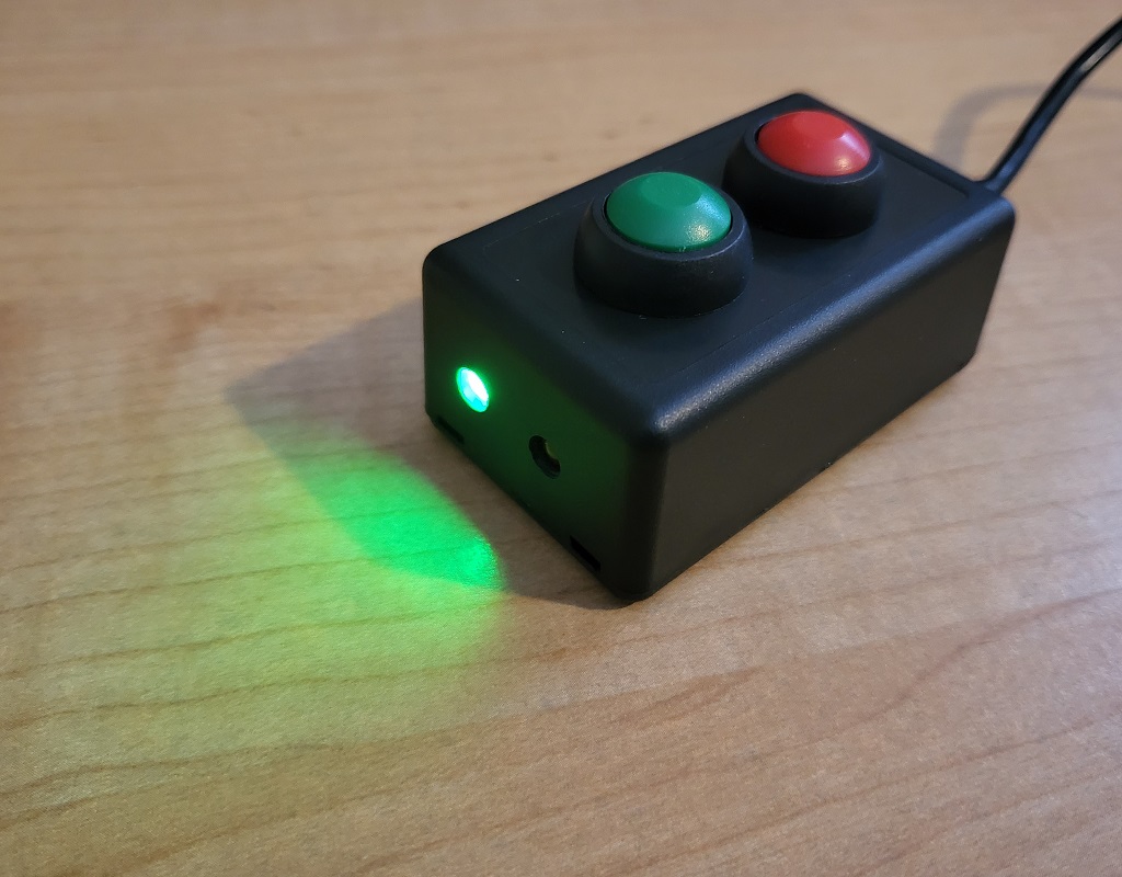
At left you can see a mock up of a version that used one LED. You could use a single LED and have it perhaps blink of success or stay lit on failure. You could also do a single LED build with an RGB LED. I elected to build this with 2 separate LEDs, so that success would turn a green LED on and failure would light up the red LED. The rest of this build – the part about sending emails and reading buttons is available in this post.
I’ve broken this guide out into 2 parts: Software and Hardware. First, lets get our tools and materials together.
Tools Required:
- Hot glue gun
- Soldering Iron
- Basic Wire Stripper
- Small Drill Bits
- Any Drill – this is the one I use.
Parts Required:
You’ll need everything from this project, plus the list below.
- Some LEDs. I used one red one and one green one.
- A couple 220 Ohm resistors.
- Hookup wire. I like this one because its very flexible.
- You could also opt for a small kit like this, instead of buying individual pieces. This one includes some wire, resistors and LEDs already, among other things. Handy stuff to have around if you are going to do more electronics projects. I like this one because it includes a breadboard compatible power supply.
Software
- At this point, you already have a working Arduino IDE environment, including drivers for your device. You’ve already used that IDE to upload your sketches to your NodeMCU or other board. You already have the SMTP Client loaded. If you haven’t done all that, take a look at this project, which walks you through it in Phase 1.
- I updated the code to include support for this dual LED build. Get that new code from the github repository here.
- The behavior of the LEDs is:
- Turn Green LED on for 10 seconds if email is sent successfully.
- Turn Red LED on for 10 seconds if there was an error sending email.
- It uses this same behavior regardless of which button you pushed.
- Even though you should have already updated these variables, I’m going to walk through them all here. Open up the .ino file you just downloaded in the Arduino IDE.
- Locate this block of code, and update with your own WIFI SSID, WIFI Password, Email Account, and Email Account Password:
|
1 2 3 4 5 6 7 8 9 10 |
/* Update these values with your WIFI information */ #define WIFI_SSID "YOUR SSID HERE" #define WIFI_PASSWORD "YOUR WIFI PASSWORD HERE" /* Update these values with your Email Sending Account information */ #define SMTP_HOST "YOUR SMTP HOST HERE" #define SMTP_PORT 465 //Update to whatever SMTP port you are using /* The sign in credentials for sender account */ #define AUTHOR_EMAIL "SENDER EMAIL" #define AUTHOR_PASSWORD "SENDER EMAIL PASSWORD" |
- Next look for the block of code below. Take a look at the pins indicated in the code. You can update these as needed to align with whatever pins you are going to use. Notice how each pin is commented? That is because the pin numbers in code don’t necessarily match the pin labels on the board. Check out section 2 below about hardware for more details.
|
1 2 3 4 5 |
// set pin numbers const int checkinPin = 14; //aka Pin D5 the number of the pushbutton pin const int checkoutPin = 12; //aka Pin D6 the number of the pushbutton pin const int greenLED = 4; //aka pin D2 for the success LED const int redLED = 5; //aka pin D1 for the error LED |
- Scroll down a bit to find this next block. These are the messages and subjects for the emails you are going to send. Edit them to your needs. Note that you CAN use HTML in the message text.
|
1 2 3 4 5 6 7 8 |
if (inbuttonState == LOW) { Serial.println("Check-In Button Was Pushed"); SendEmail("This is the text for the check-in button email", "Check-In Subject"); //Edit with your message text } if (outbuttonState == LOW) { Serial.println("Check-Out Button Was Pushed"); SendEmail("This is the text for the check-in button email", "Check-Out Subject"); //Edit with your message text } |
- Scroll down a bit more to find this block. Edit this with your recipient information.
|
1 2 3 4 5 |
message.sender.name = F("YOUR NAME"); //edit with the name of the sender message.sender.email = AUTHOR_EMAIL; message.subject = MessageSubject; //edit with the email address you are sending to message.addRecipient(F("NAME OF RECIPIENT"), F("recipient@whatever.com")); |
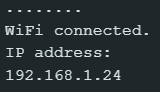
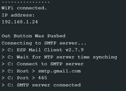
- Now you just need to upload this code to your board. Go to sketch->upload and cross your fingers while you wait for it to do its thing. If all goes well, move on to the next step. If there are errors, troubleshoot them! If it works, you should see something like this in the serial monitor, indicating that you are on the WIFI and have an IP address. That is all this sketch will do until we get the buttons hooked up in the next section.
Hardware
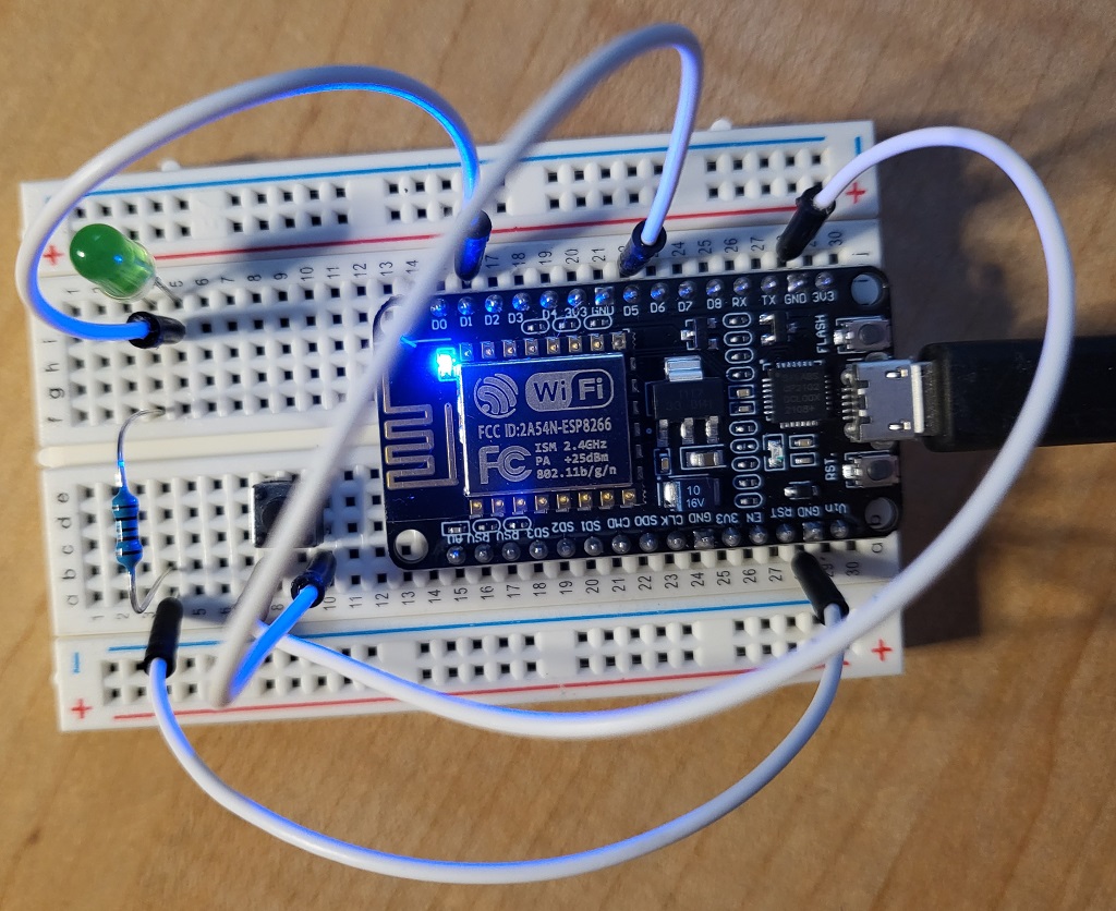
- Start by wiring up your buttons as shown below. You may want to mock it all up on a breadboard first, to make sure you have all your pins correct in code.
- Add 220 Ohm resistors on the anode (-) leg of the LEDs. Those resistors will be between the anode leg and ground from the NodeMCU.
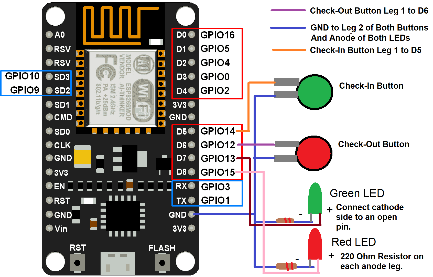
NOTE: The pin numbers printed on the board do not match the internal GPIO numbers. Once you’ve wired up your device, go into code and update whatever pin numbers you used. For example, if my wiring looks exactly like this diagram, then my code would look like this:
|
1 2 3 4 5 |
// set pin numbers const int checkinPin = 14; //aka Pin D5 the number of the pushbutton pin const int checkoutPin = 12; //aka Pin D6 the number of the pushbutton pin const int greenLED = 13; //aka pin D7 for the success LED const int redLED = 15; //aka pin D8 for the error LED |
- Now that your pins and hardware are in alignment, upload your code to your board. If everything is working, you will see something like this:
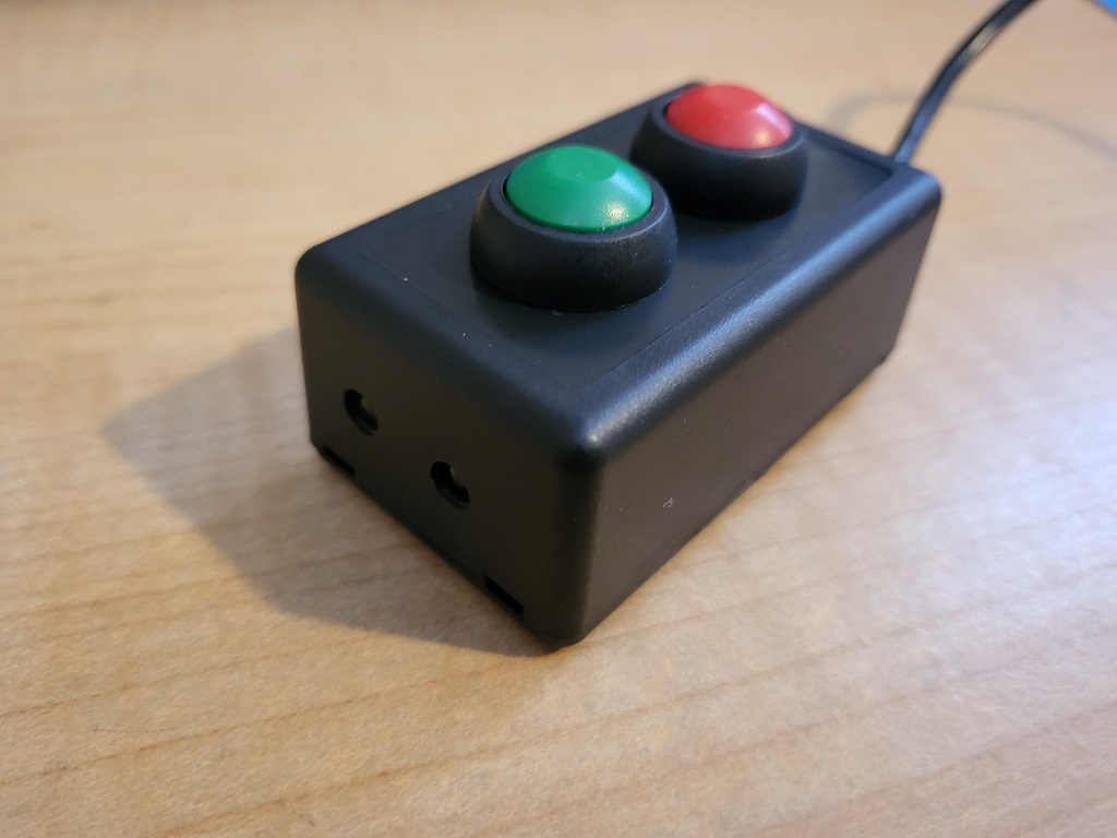
- In my build, as you can see from the finished product image below, I drilled a separate hole for each LED. Inside the box, I secured those LEDs with hot glue.
Thats it! At this point, you should have a cool little device with 2 buttons that sends a different email depending on which button you push. Once you push a button, it will light a status LED to let you know if the email was sent successfully. Have any questions or suggestions? Let me know in the comments section below!
[…] ** UPDATE ** I added some status LEDs to this device in a new post located here. […]
Have you thought about using an LCD screen (https://www.amazon.com/HiLetgo-Display-Bluetooth-Internet-Development/dp/B07X1W16QS/ref=sr_1_4?keywords=esp32+screen&qid=1680539688&sprefix=esp32+scree%2Caps%2C101&sr=8-4) on the ESP32 to get feedback? Yes, the LED diode keeps it super simple, but a screen could show you that feedback you had in the screenshot.
I’m wondering if for your use case you can automate the email alert with a sensor. Maybe a human sensor or a door magnetic switch would work and save yourself the repetitive stress of pressing a button.
Works Awesome thank you ! I hope to use this sketch for a sump pump alarm to send me an email when the level is too high